所屬科目:研究所、轉學考(插大)◆控制系統與數位邏輯
Problem 1: system transfer function with initial conditions (10 points) Given a linear system with system input-output transfer function; compute outputy(t),t≥0with initial conditions: y(0)=1,,and zero input, u(t)=0, t≥0.
Problem 2: time and frequency responses (10 points) Consider a control system with system transfer function ;find frequency response bandwidth and maximum overshoot MO% for unit-step response.
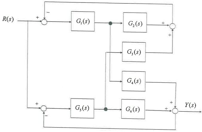
Problem 3: System block diagram (10 points) the input-output transfer function T(s) = Y(s) / R(s) of the system block diagram below .
Problem 4: Root-locus analysis (10 points) Consider a negative unity-feedback system, , with loop transfer function ; draw the root-locus of T(s) for 0 < K <∞.For higher score,the root-locus should be as detailed as possible.
Problem 5: Root-locus design (10 points) Continue on Problem 4, design K such that the unit step response y(t) of the closed-loop system, T(s), having zero steady-state error, zero maximum overshoot MO = 0% and 3dB bandwidth rad/sec.
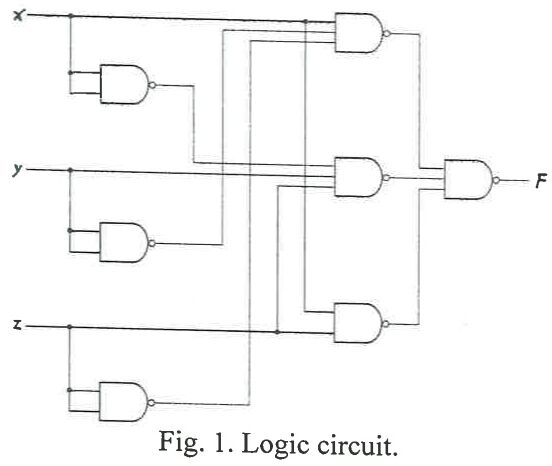
Problem 6 (10 points) Find F(x,y,z) in Fig. 1. You must present the details.
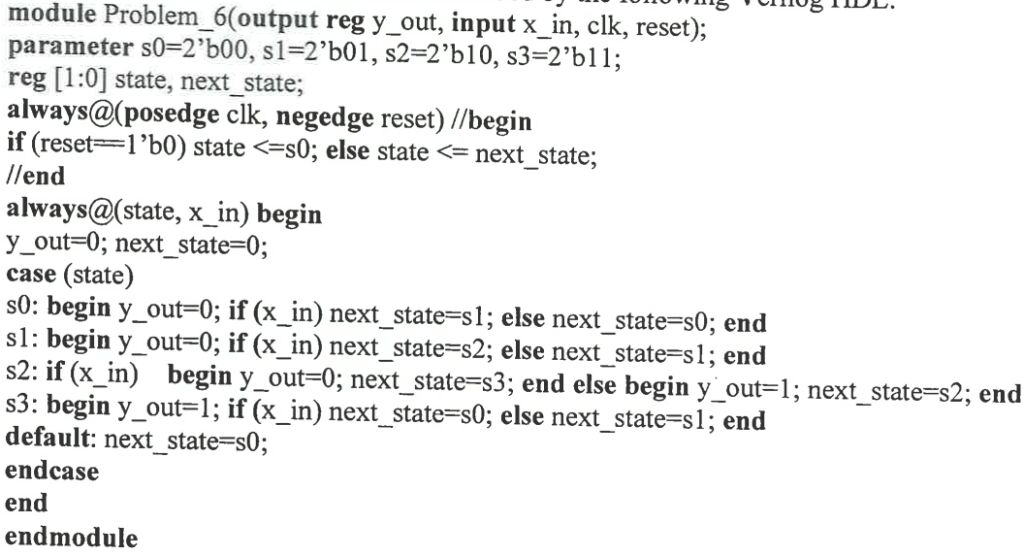
Fig. 1. Logic circuit. Problem 7 (12 points) Draw the state diagram of the machine described by the following Verilog HDL.
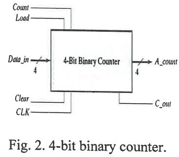
Problem 8 (13 points) InFig. 2, a 4-bit binary counter with Load (L), Count (C), data inputIi,i = 0,1,2,3, and output Ai,i = 0,1,2,3 is presented. Its function table is in Table 1. How to use and some logic gates to count from 0 to 134, and then back to 0. Daint 4-Bit Binary Counter + A_cOmr Clear Load Count Function Clear to 0 Load inputs Count nexi binary state Table 1. Function table of 4-bit binary counter. No change XX1O XIOO Xtii Fig. 2.4-bit binary counter.
 阿摩線上測驗
登入
阿摩線上測驗
登入
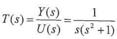 ; compute outputy(t),t≥0with initial conditions: y(0)=1,
 ,and zero input, u(t)=0, t≥0.
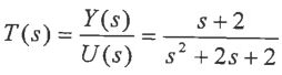 ;find frequency response bandwidth
 and maximum overshoot MO% for unit-step response.
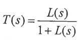 , with loop transfer function
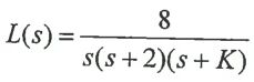 ; draw the root-locus of T(s) for 0 < K <∞.For higher score,the root-locus should be as detailed as possible.
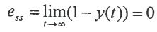 , zero maximum overshoot MO = 0% and 3dB bandwidth
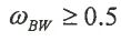 rad/sec.